2025 Updates
1.1 License Server Window: Interactive Resizing (2144)
The license server window can now be interactively resized by the user.
To do this, the user must left-click in the bottom-right corner of the window, hold the mouse button down, and adjust the window to the desired size.
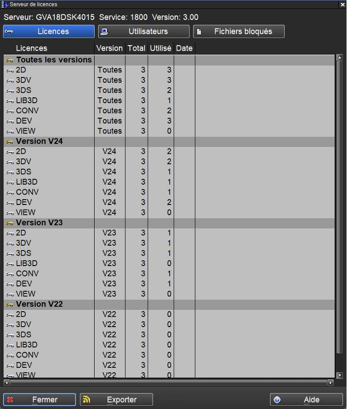
1.2 License Server Window: Display Update (2144)
In the “Licenses” tab of the license server window, the information is now grouped by “version” to provide users with a clearer and more user-friendly view.
1.3 The “Desktop Size” feature is now available in VIEW mode (2454)
A user with a VIEW license (consultation mode) can now use the “Desktop Size” feature (2454). This feature allows switching between the original size (normal mode) and a doubled size (UHD mode) for icons, cursor, and text.
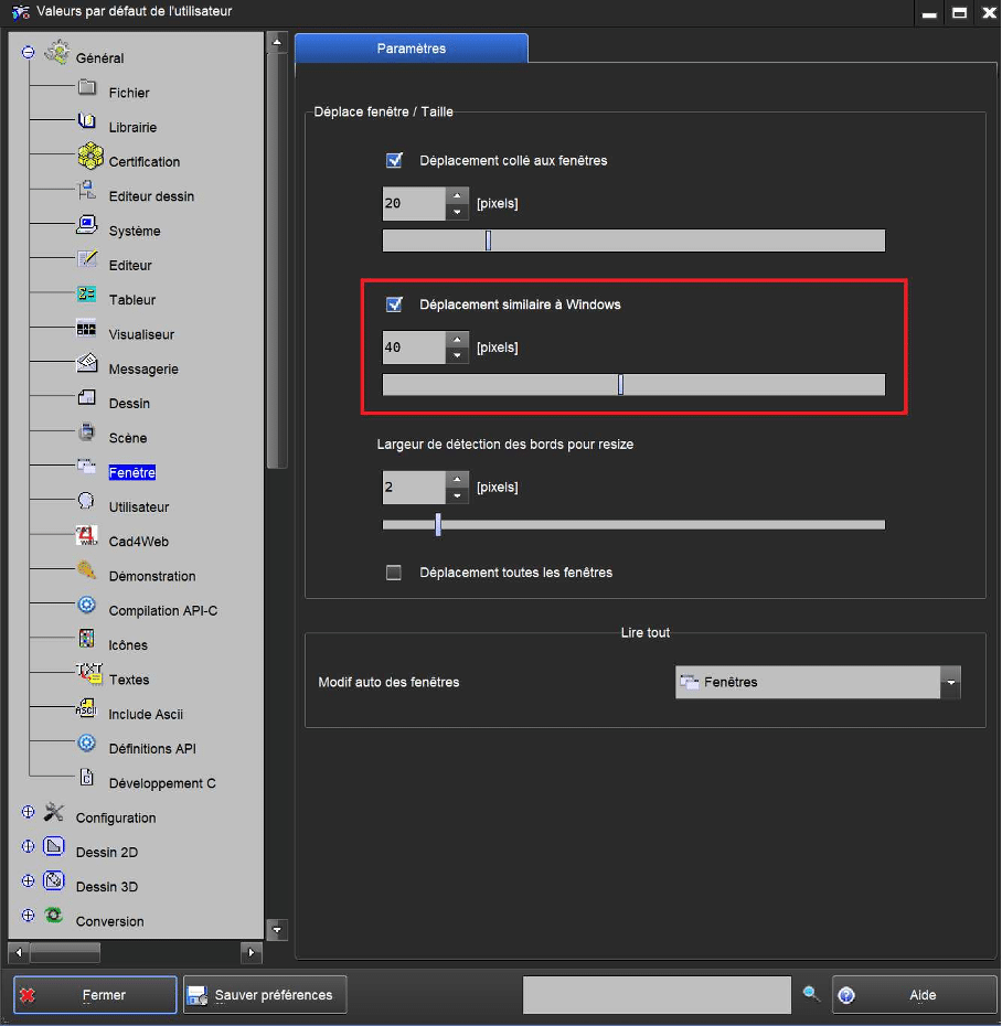
1.4 Interactive Positioning of 2D-3D Windows
Just like in Windows, the positioning of 2D and 3D windows in Tell can now be done interactively using predefined layout schemes.

To do this, the user can drag a 2D or 3D window toward the top edge of the drawing area, then select a predefined layout scheme.
To do this, the “Windows-like window movement” option must be enabled (enabled by default).
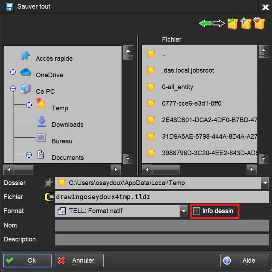
1.5 Addition of a “Drawing Info” Option in the “Save All” Window (35)
To reduce confusion and the risk of errors when saving a drawing, a “Drawing Info” option has been added to the file save window.
This option allows users to enable or disable optional fields (drawing name and description).
By default, this option is disabled.
The state of this option is saved in the user preferences.
2. Preferences
2.1 Languages (275)
Addition of the Portuguese Language

3. 3D
3.1 Display of Planar Reflection of Parts in Your 3D Drawing
It is now possible to display the reflection of parts in your drawing along a horizontal plane.
3.2 Addition of Shadow for 3D FEM Elements
Shadow display has been added for 3D finite element (FEM) elements.
4. Drawing
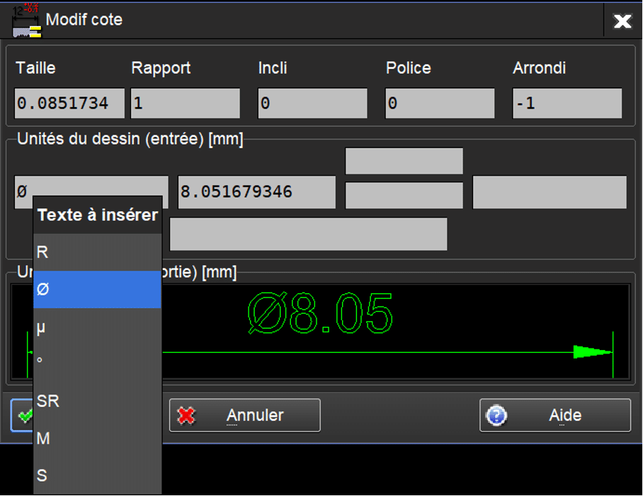
4.1 Special Characters When Editing Dimensions (344)
When editing a dimension, it is now possible to insert a special character in the first field of the dimension label.
Among others, it is possible to insert the Ø symbol.
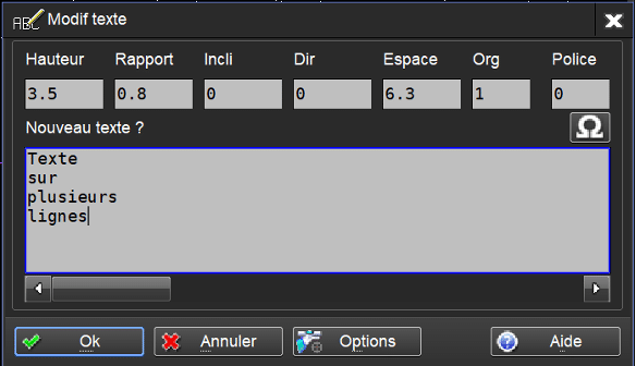
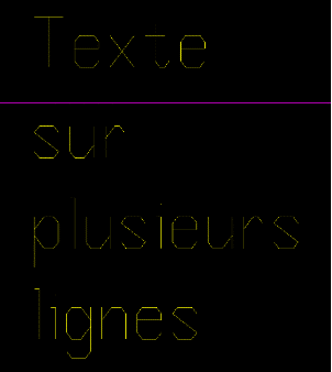
4.2 Multiline Text When Editing or Modifying Text (102 and 103)
When editing or modifying text, the user can now edit text on multiple lines.
5. Watchmaking
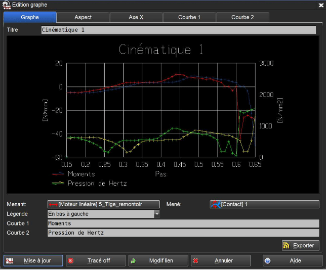
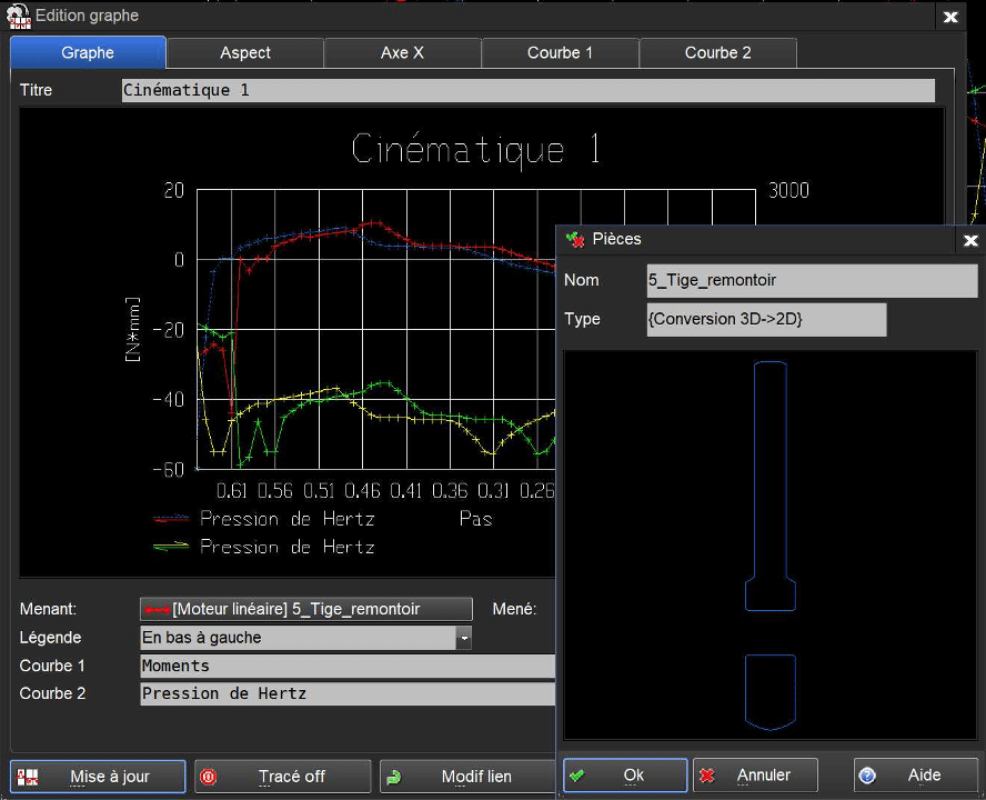
5.1 New Design for the Graph Editing Window (1100)
The graph editing window has been redesigned so that, for each tab, the information provided and the values to be specified—and thus the usage—are much more consistent and intuitive for users.
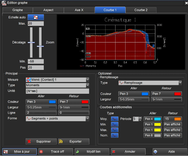
5.2 New Feature in the Graph Editing Window: Interactive Resizing (1100)
The graph editing window can now be interactively resized by the user.
To do this, the user must click in the bottom-right corner of the window, hold the mouse button down, and adjust the window to the desired size.
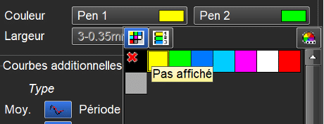
5.3 New Feature in the Graph Editing Window: Colors for Additional Curves (1100)
The user can now choose the colors for each of the additional curves, for both the “forward” and “return” directions.
There is a palette of 10 colors available—2 colors for each additional curve. These additional curves are:
- Average curves
- Maximum value curves
- Minimum value curves
- Nominal value curves
- Yield limit (only in the case of a Von Mises calculation)
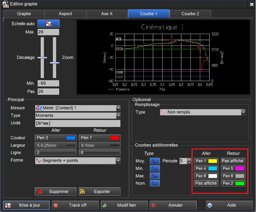
5.4 New Feature in the Graph Editing Window: Hide Curve Option (1100)
It is now possible for the user to hide a curve. To do this, the user can click on the associated color field and select the first item in the list (“not displayed”).
5.5 New Feature in the Graph Editing Window: Visualization of Link Entities (1100)
By clicking in the fields next to the “driving” and “driven” texts in the ‘Graph’ tab, the user can now visualize the selected driving and driven entities.
5.6 Terminology Change in Graphs (1100)
For greater clarity, the measurement texts “Forces” and “Directional Forces” have been replaced by “Force (magnitude)” and “Force (component)” in the graph editing window.
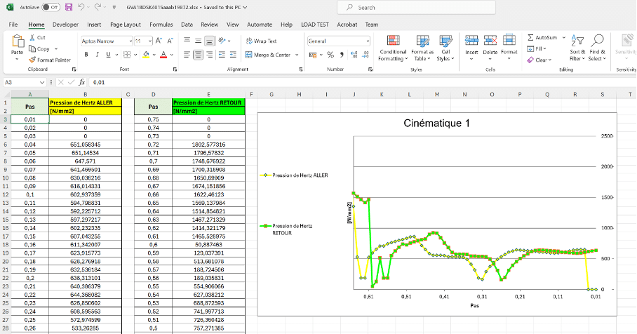
5.7 New Feature in the Graph Editing Window: Export Data in .xlsx Format (1100)
When exporting to Excel .xlsx format, the colors and curve display in Excel now match those in TellWatch.
5.8 New Feature in the Graph Editing Window: Dynamic Display of Curve Tabs (1100)
In the graph editing window, the number of curve tabs displayed is now dynamic.
These tabs vary depending on the measurement curves.
In some cases, the “Curve 2” tab will be present, along with “+” and “−” buttons to add or remove the “Curve 2” tab.


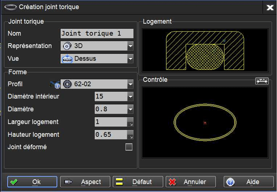
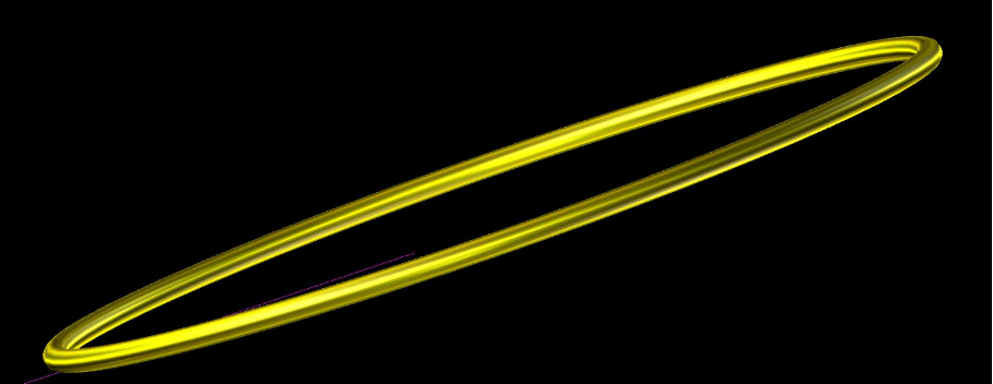
5.9 New Component: “O-Ring” (2540)
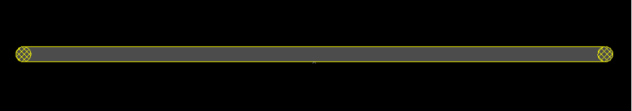
5.10 New Component: “Ferrule” (2541)
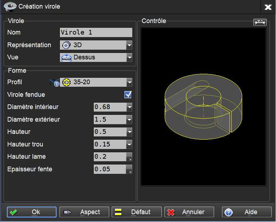
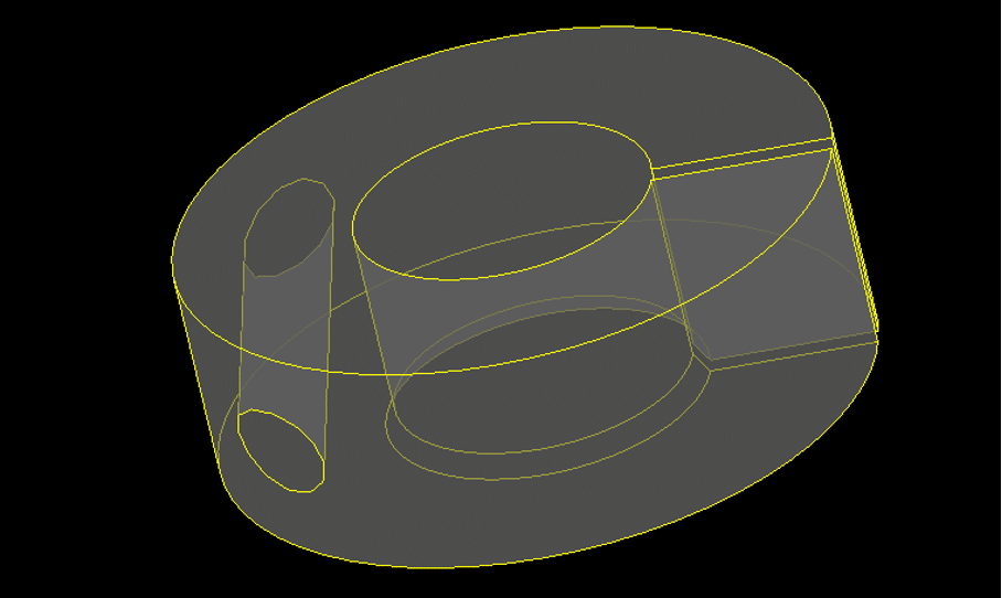
5.11 Interactive Selection of Component Parameters via Dimensions in the Control Window
When creating certain components in 2D representation, the parameter value fields can be interactively selected by the user by clicking on the associated dimension shown in the component’s control window.
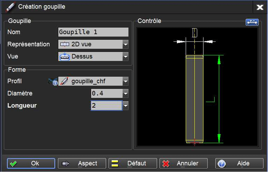
To do this, the visualization of parameters by dimension must be enabled: click on the icon at the top of the Control window.
This feature is currently implemented for the components Pin, Drum, Bar, and Ferrule.
6. Kinematics
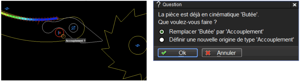
6.1 Kinematic Definition (1325): New Origin
It is no longer necessary to draw the entities serving as the origin.
The function automatically detects, for most kinematic types, the type of new origin (pivot, coupling) to apply and creates the origin entities automatically.
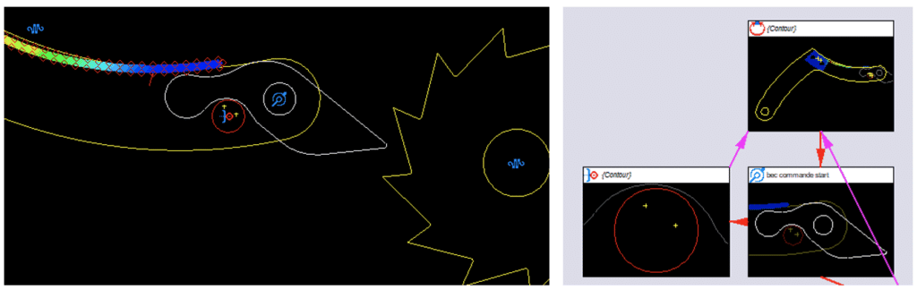

Addition of Display for the Type of New Origin Created.
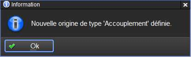
The new origins can be created using the kinematic definitions “Pivot” and “Coupling.”
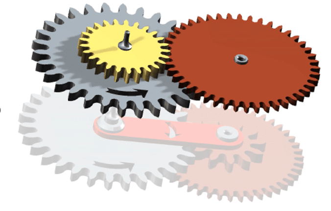
6.2 Rotary Spring in Dynamic Kinematics
The “rotary spring” kinematic is now supported in the kinematic calculation called “dynamic” mode.
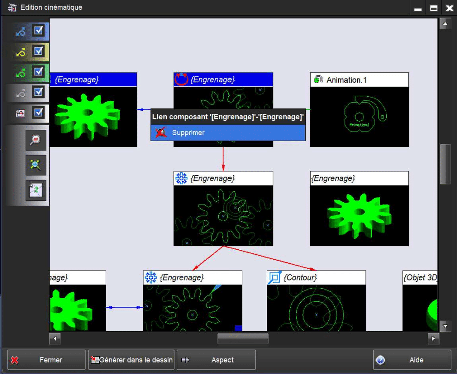
6.1 Ability to Delete a “Component Link” or “2D-3D Link” in the Kinematics Editing Window (1105)
In the kinematics editing window, it is now possible to delete an existing component link or 2D-3D link (blue connection).
To do this, the user must click on the link using the mouse’s “Modify” button and select “Delete” in the pop-up window.
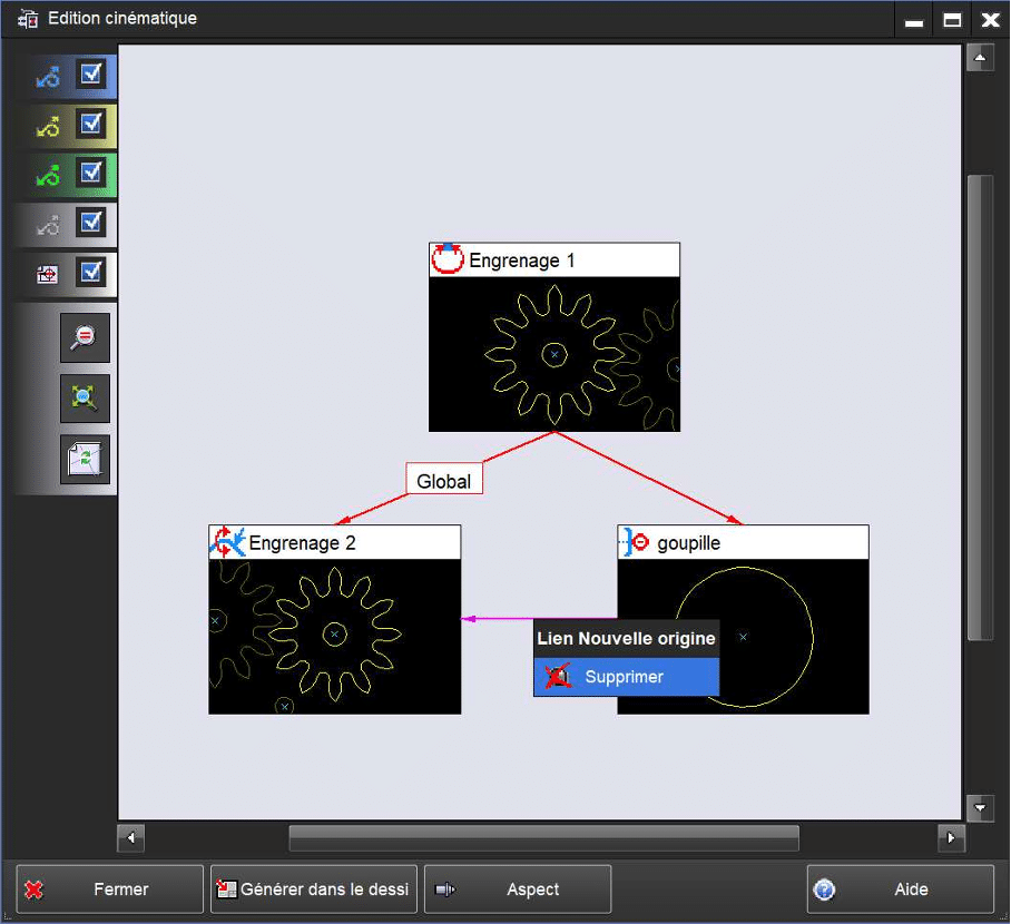
6.2 Ability to Delete the New Origin Definition in the Kinematics Editing Window (1105)
In the kinematics editing window, it is now possible to delete the new origin definition on a part (pink link).
To do this, the user must click on the ‘new origin link’ using the mouse’s “Modify” button and select “Delete” in the pop-up window.
6.3 Ability to Perform “3D Object Alignment” on Its Linked 2D View in the Kinematics Editing Window (2192)
In the kinematics editing window, it is now possible to align/position a 3D object on its linked 2D view.
To do this, the user must click on the 3D object linked to a 2D view using the mouse’s “Modify” button and select “Object Alignment” in the pop-up window. The 3D object will then be positioned/aligned on its linked 2D view.
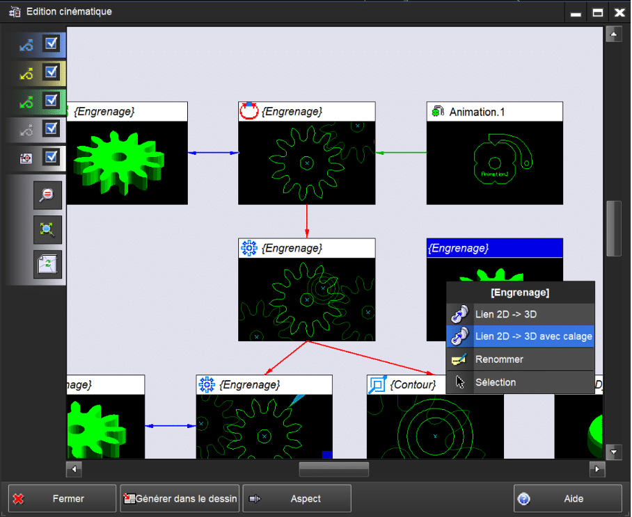
6.4 Ability to Create a “2D→3D Link with 3D Object Alignment” on the 2D View in the Kinematics Editing Window (2544)
In the kinematics editing window, it is now possible to link a 3D object to a 2D view while aligning/positioning it on that view.
To do this, the user must click on an unlinked 3D object using the mouse’s “Modify” button, select “2D-3D Link with Alignment” in the pop-up window, then click on the 2D view to which they want to link it. The 3D object will then be linked and positioned/aligned on the 2D view.
7. Additional Module: Kinematics+
7.1 Multi-Motor Kinematics
The kinematics module now allows simulation of mechanisms with multiple motors within the same calculation.